Collisions
Most of the following are my personal notes on Jeff Wagners awesome masterclass on Collisions. It’s a bit on the longer side of presentations (6ish hours in 3 parts), but I highly recommend watching it! It also comes with demo files and a PDF which I will quote multiple times below.
# How Colliders are built in DOPs
DOPs is set up in a way that most HDAs are built from an empty object. Then there is data added to it. “Data” can mean loads of things:
- geometry
- physical simulation parameters
- display geometry
- render parameters to define what is visualized in the viewport
# Ground Plane
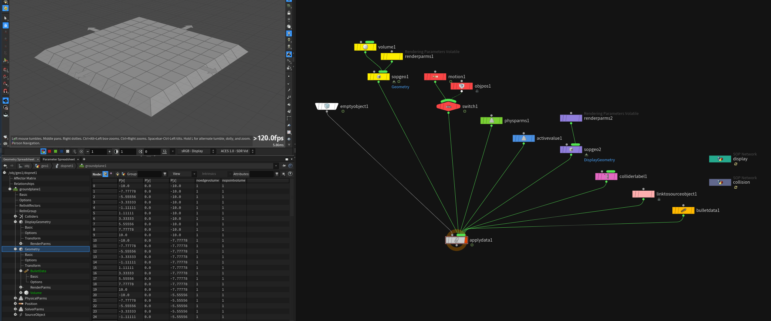
- (yellow) creates volume collision data and sets render parms to make it invisible in the viewport
- (red) applies motion/position data (also from OBJ level)
- (green) applies physical parameters such as
bounceandfriciton - (blue) can be used to turn object active
- (purple) fetches display geometry and sets render parms
- (pink) labels collider
- (peach) stores info where the DOP object comes from
- (orange) bullet collision setup
- (dark green) display geometry SOP network
- (grey blue) collision geometry SOP network
This is just a sparse overview to go back to. To really understand it watch part 1 of Jeff Wagner’s presentation (00:12:00 - 00:25:00).
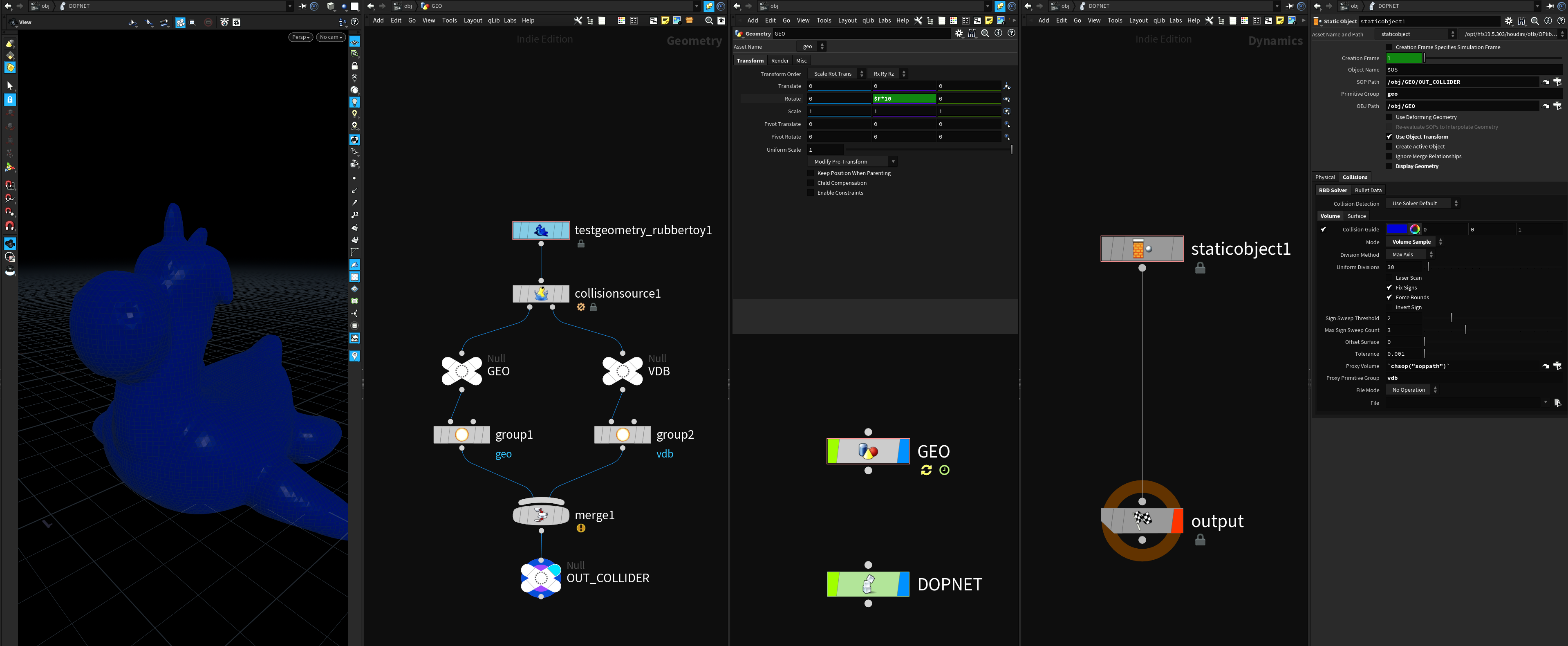
# Static Object
The static object DOP is a little bit more involved then the ground plane, but it’s based on the same concepts .. just with more boilerplate nodes and switch logic around it.
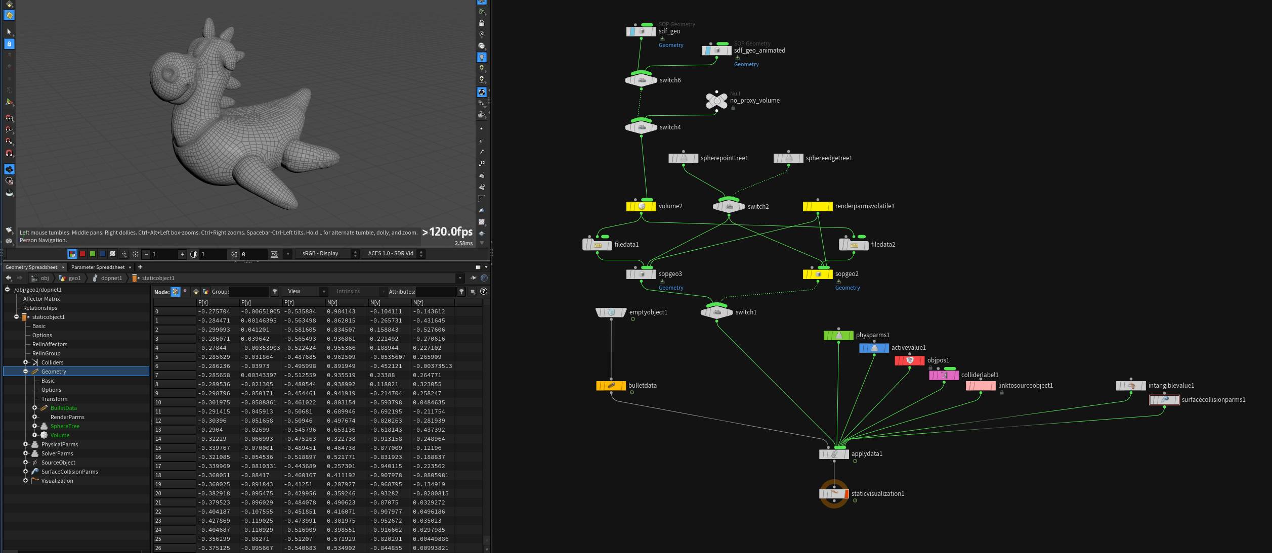
I matched the node colors to show the similarities.
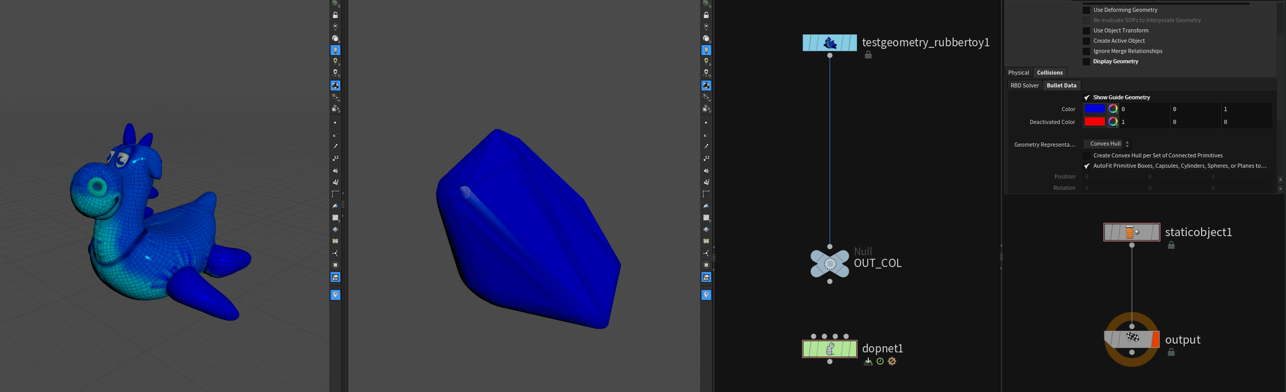
# Deforming Object
This just exists as a shelf tool which sets up the static object DOP correctly to account for transformations and deformations.
# Different Solvers Expect Different Colliders
# POP Solver
Supported Collision data:
- SDF Volume geometry (default)
- very fast, real 3D
- Height Fields (same as SDF Volume data)
- very fast but no holes
- only
unchanged,stop,dieresponse / hit behaviour work
- Polygonal geometry
- slow ( has to calculate primitive, primuvs for each particle )
- can be used for complex systems that depend on per hit data like
hitnormaletc. slide,stickresponse / hit behaviour only works with polygons
Particle simulations tend to be either of the following two types:
- A LOT of dumb particles
- A FEW smart particles
// from the SideFX pdf:
Dumb particles have no real rules other than forces motivating them through space. Using the default SDF Volume type colliders is the preferred method. The test to see if a particle is in or out of an SDF is a continuous linear lookup. The solver can predict when a particle is about to go from +ve outside space to =ve inside space of the SDF Volume. Remember the SDF is built from surface geometry. It encodes the surface upon SDF creation so all the hard work has been done. Am I in or out? SDF look up is almost instantaneous.
If you have smart particles with lots of rules especially around collisions, you can choose to use polygons. When you collide against polygons, you can inherit the bi-linearly interpolated attribute values from the polygon faces. This means that you need to record the polygon face number and the actual local u and v hit co-ordinates on that polygon face.
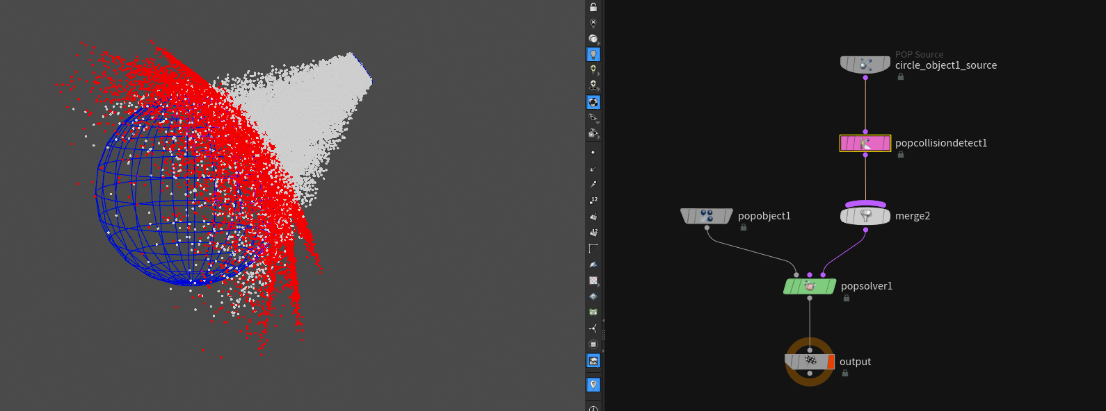
To make particles collide with polygons you can use the POP Collision Detect DOP in the pop source stream of the simulation. Just give it a SOP path and it should work.
# Particle Orientations and Collisions
// from the SideFX pdf:
When particles collide against a surface, the velocity vector of the particle is mirrored along the hit normal or the tangent of the face. This works for both SDF Volume colliders and polygonal surface colliders.
By default, any instanced or copied geometry to these points will use the
vvelocity attribute to orient the geometry, if there is novector4 orientquaternion attribute on the geometry
# Grain and Wire Solver
Grains uses the pop solver and the wire solver behaves like POPs so the same rules apply to both.
Supported Collision data:
- SDF Volume geometry (default)
- Height Fields (same as SDF Volume data)
- Polygonal geometry
# FLIP Solver
Unlike the POP Solver which can take different but separate collider types the FLIP solver needs polygonal geometry AND a surface vdb!
Supported Collision data:
- SDF Volume data for surface collisions
- Height Fields (same as SDF Volume data)
- Volume Velocity Fields
- (Polygon surfaces through POP Collision Detect but at your own peril)
On the FLIP solver under Volume Motion > Collision you can specify where to read the collision velocities from (Point or Volume).
// from the SideFX pdf:
The main issue is resolution. For test FLIP sims and detailed colliders, you will not have enough collision detail. You have to enable.
Thin colliders like cups and vessels containing fluid can benefit from: • Thick boundary walls. • if moving fast, lots of substeps and blending between frames. (Default shelf setup). • Extra velocity on the collider adding in some surface normals to the velocity.
To avoid precision errors make sure to simulate in a moderate scene scale ( not too small or too big ). I wrote a little more about it here.
# PYRO Solver
Supported Collision data:
- SDF Volume data for surface collisions
- Height Fields (same as SDF Volume data)
- Volume Velocity Fields
// from the SideFX pdf:
You can use particles as collider sources using the
Gas Particle To FieldDOP to take your points and convert them in to SDF collision fields for use by the Pyro Solver.You need to name the field “collision”.
If you go this route, you also have to use a second
Gas Particle To FieldDOP to construct a companion “collisionvel” vector field to hold the velocity of your collider. […]Same goes for FLIP colliders. How these merge in to other existing collision and collisionvel fields is determined by how you mix these in with the
Gas Linear CombinationDOP
# VELLUM Solver
VELLUM is an XPBD (Extended Position-Based Dynamics) solver.
Supported Collision data:
- Polygonal geometry
as the name “position based” suggests there is no way to use sdf volumes as colliders, because they are only represented as a single point in Houdini.
There isn’t much to take care of except making sure that you have a consistent point count on the collider geometry.
You can use the POP Collision Ignore node in DOPs to specify which vellum geometry is affected by which collider. Read more
here.
# CLOTH Solver
Cloth supported Collision data:
- Cloth colliders from the Cloth shelf
- Polygonal geometry (supports swept collisions for sub-frame interpolation)
- SDF Volume data for surface collisions
- Height Fields (same as SDF Volume data)
- Volume Velocity Fields
Cloth solver (subset of the Solid FEM solver) is a special solver that prefers to collide against other cloth objects.
# SOLID (FEM) Solver
Solid supported Collision data:
- Solid colliders from the Solid shelf
- Polygonal geometry (supports swept collisions for sub-frame interpolation)
- SDF Volume data for surface collisions
- Height Fields (same as SDF Volume data)
- Volume Velocity Fields
// from the SideFX pdf:
The Solid solver uses FEM or Finite Element Methods to stimulate different materials from soft fleshy objects to concrete and everything in between.
Collisions with like tet objects that are very rigid is a robust way of managing collisions. But many times we wish to integrate the Solid solver with other collision data such as polygon data. You have two choices: Use the Collision Shelf Static or Deforming tools to introduce polygon colliders, or use the Solid shelf and create a static solid collider comprised of tets.
# Rigid Body (BULLET) Solver
Supported Collision data:
- Bullet Collision data (solver specific)
- Height Fields
Different Collider Types:
- Geometry Based
- Convex Hull
- Concave (not recommended)
- Primitive Types
- Box
- Capsule
- Cylinder
- Compound (important!)
- Sphere
- Plane
- SDF Based
- Height Field
# Solver Substeps:
Global Substeps x Bullet Substeps = Total Substeps
Important to resolve collisions / interpenetration / tunneling => especially when lots of different objects are close to each other.
Bullet substeps work like this:
N = number of bullet substeps
- Take 1 global substep and divide it in N bullet substeps
- Take the velocity and divide it through N as well
- Move geometry forward N times by velocity/N and resolve collisions after each step
recommended minimum: 10
# Height Fields as Bullet Colliders:
// from the SideFX pdf:
Height fields make excellent bullet colliders. You can represent complex surfaces with height fields for efficient bullet simulations.
Your only limitation is with height fields themselves. They do not support overhangs. The height fields by their nature are both concave and convex. It is good to know that there is a very fast solution to describing terrain collisions in Bullet without resorting to creating manifold terrain colliders.
As with infinite plane colliders, you can use several height fields to define collision planes in your Bullet simulations.
Just like infinite planes, these height field colliders have an inside and an outside. You can think of these as SDF colliders defined by a single voxel high volume.
Unlike infinite planes, height fields are not infinite. The size of the height field is what the bullet solver uses. Any collisions beyond the height field will will not be by that height field.
You can use the Terrain Object shelf tool under the Collisions to set this up correctly.
# Concave Colliders with Convex Hulls
Default bullet colliders are convex:
To work around this without sacrificing performance too much there are two similar ways. Both split up the geometry into smaller pieces which will be “convex hulled” separately. Make sure to enable Create Convex Hull per Set of Connected Primitives!
- Voronoi Fracture
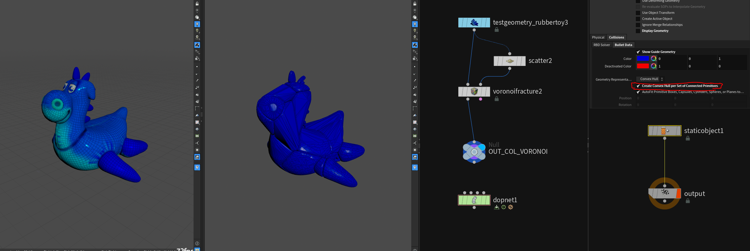
- Convex Decomposition
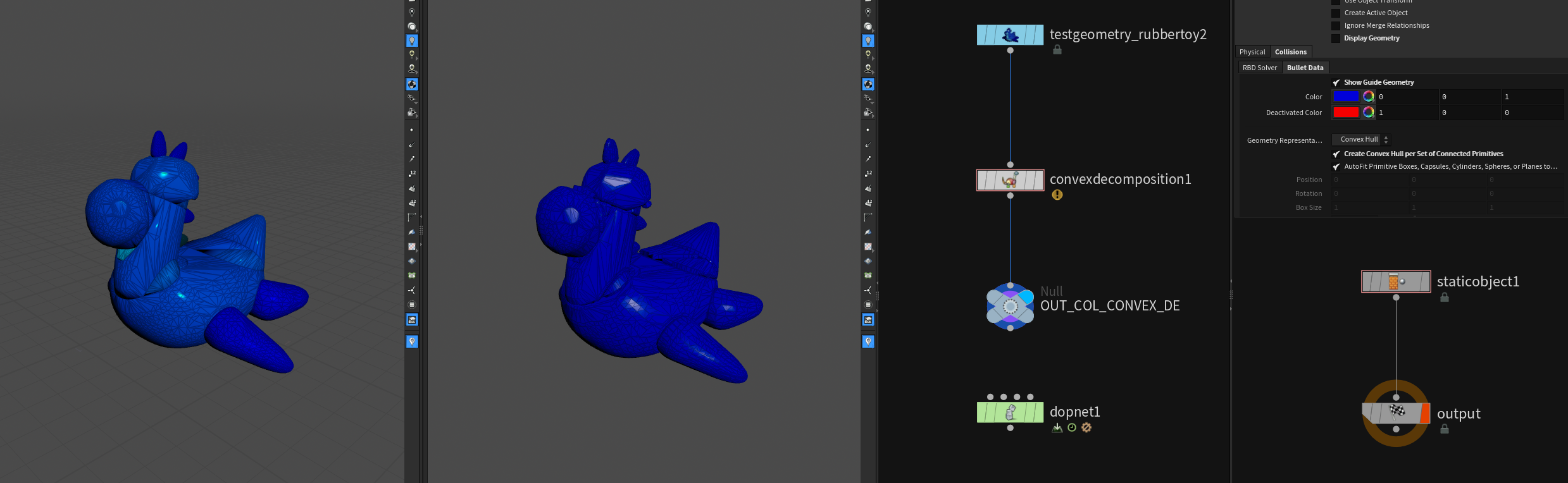
You can also use boolean operations or develop your own algorithm that splits up the geometry into mostly convex pieces.
# Concave Colliders with Spheres
If you need fast but pretty accurate collisions in RBD sims you can generate loads of little spheres inside the geometry and use those as a compound to calculate collisions. In fact this is the fastest way to calculate collisions, because you only need to know 1 point and the radius to calculate where collisions would occur.
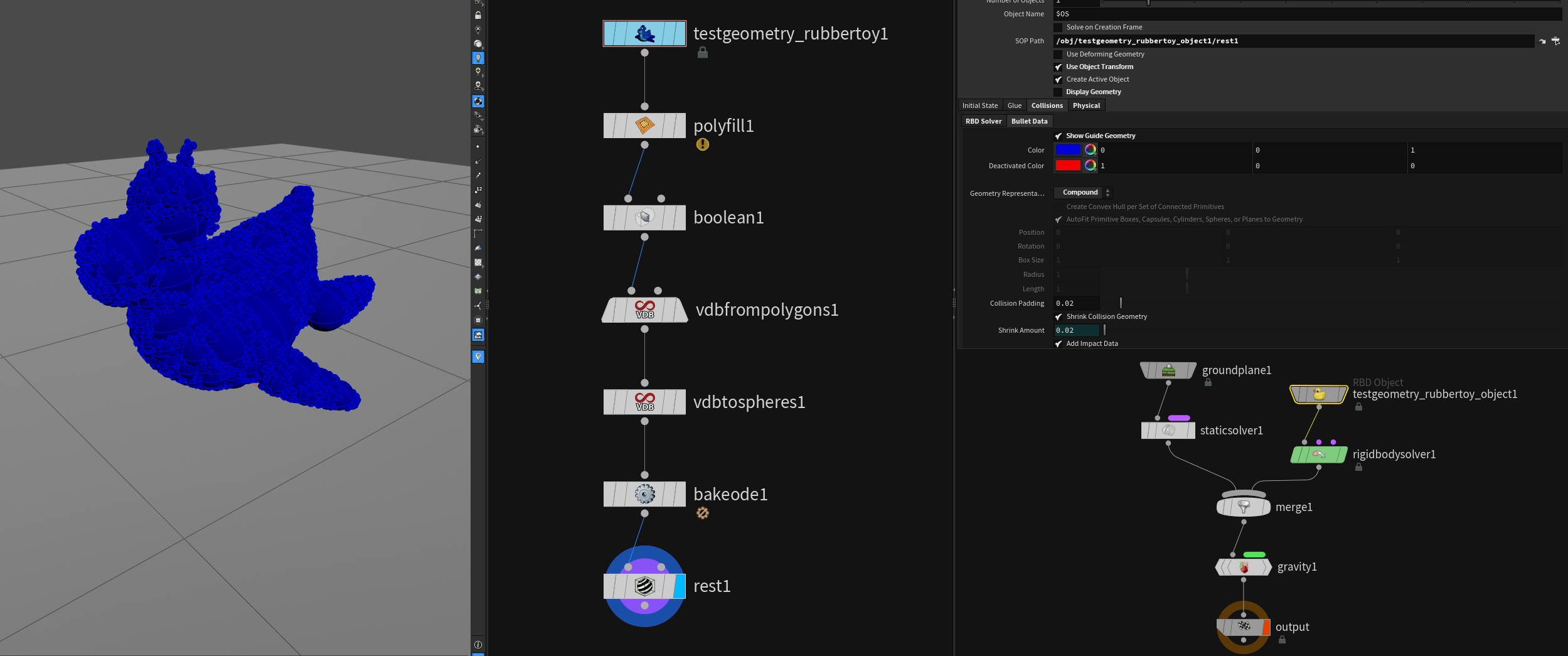
Make sure to use bake ODE and set the Geometry Representation on the RBD Object to Compound.
You can then apply the transformation back to the original geometry by using extract transform for example.
# BULLET Collision Objects and other Solvers
List of possible combinations with bullet colliders:
- bullet and particles
- bullet and grains
- bullet and wires
- bullet and flip fluids
- bullet and pyro
- bullet and cloth
- bullet and solids (FEM)
# BULLET and Particles or Grains
Particles collide quite well against bullet simulation objects.
# BULLET and Wires
Wires collide against bullet objects, but there won’t be any mutual affection. It’s hard to get this working without extensive sop solver trickery and extremely light bullet pieces. Use VELLUM instead!
# BULLET and FLIP
FLIP uses the Bullet collision geometry to build it’s colliders. When using packed RBD objects the geometry you see in the viewport only exists on the GPU, which is why FLIP can’t access it. Same thing applies to pyro.
# BULLET and Pyro
BULLET objects collide the same way as in FLIP. No access to packed geometry.
# BULLET and Solids (FEM) and Cloth
Possible. Needs higher number of substeps on DOP network to get stable results. Subdivided geometry can help improving interaction, because the solid solver uses polygons to calculate collisions (too few points = inaccurate collisions).
# BULLET and VELLUM
Mutual VELLUM - BULLET interaction is unfortunately not possible. You can somewhat fake it but it will always be a hacky workaround.
By now you can use Shape Match Constraints and Vellum Transform Pieces in VELLUM to achieve a similar look, though. Check out
John Lynch’s Talk about the topic!
# Colliders and Substeps
# Substepping
There are two areas where you can find substepping:
- The global substep rate used to march all solvers forward.
- Local solver substepping
Both of these have ramifications when it comes to collision geometry that is either animated or deforming. Static geometry is static so no issues there.
# Global vs Solver Substeps
Global Substeps = Set on the DOP network / affects all microsolvers etc. end to end
Solver Substeps = Set on each micro solver or DOP object / affects only sub objects (closed system)
// from the SideFX pdf:
Global substeps are easy to understand. The global substep rate is set at the top level DOP Network folder node. The node that contains the entire DOP network.
This rate forces all the solvers to sync up at these points in time.
Colliders are fetched from their SOP sources at these points. All the geometry for all the colliders is refreshed at these global substeps. Yes you can inject any geometry you like. Remove colliders, introduce new colliders. Your imagination is your only limit. In general colliders should move gracefully through your simulation. Solvers like that.
Solver substeps are solver specific substeps that divide up the time between global substeps in to smaller steps. Solver substeps are used for stability and accuracy within the solver.
FLIP solvers can be run at 2 or more substeps to prevent instability between global substeps. Actually in some cases will run 100 or more internal substeps.
Bullet Solver makes good use of substeps to prevent instability.
Solver substeps can be imagined as running in their own little world only communicating with the rest of the world at the global substeps. They will digest all their constraints including collision geometry and manage them in their own way.
# Viewport Debugging (Playback Rate)
To display substepped collision geometry you have to change the playback rate in the playbar options. You can set the rate to match the sub-frame global rate you set in the dop settings.
# Collider Substep Interpolation
By default colliders are interpolated linearly, which works fine in most cases where objects move somewhat straight. If you need finer control it’s best to cache out the colliders with substeps. More in the next section.
// from the SideFX pdf:
If you are using the default shelf setup for deforming colliders, you are getting linear blending between frames. For most fast moving objects, this works because fast moving objects tend to travel relatively straight. But we are in VFX and directors want snappy animation and powerful movement.
In this case where you have snappy colliders moving very fast, that linear interpolation between frames can spell trouble. What you have is a trajectory that looks like a polygon curve with points at the frames and linear sequences. Those abrupt changes at the frames can do a lot of damage. Especially if an object is animated to stop almost instantaneously and then reflected upward or back.
That instantaneous change at the frame creates an almost infinite amount of energy that may cause issues
# Smoothing Out Fast Moving Colliders
To smooth out the motion of your colliders you have a few approaches:
- Cache out your colliders at subframes to minimize the abrupt changes.
- remember to change file cache
$Fvariable to$FFto ensure correct file naming
- remember to change file cache
- Rework your colliders to use animation curves for the transforms.
// from the SideFX pdf:
If your geometry is deforming rapidly in size, scaling up or down, then your only resort is the first option.
Actually the first option works well in most cases. Even providing one extra subframe of data works well.
# Deforming Colliders
If you need volume data for colliders always cache them to disk to improve performance! Also make sure to construct and provide a collisionVel velocity volume.
Each Solver deals with deforming collision geometry differently but there is a choice as to how we bring deforming geometry in to the Simulation environment:
- Deforming geometry cached to disk
- Animated geometry at the object level
- Crowd Agents
// from the SideFX pdf:
Many of the solvers have to deal with collision data as volume SDF data either as VDB caches or our own volume SDF caches. This is one area where VDB shines and is the recommended workflow both for less memory both on disk and in memory and the speed of VDB cache creation and loading from disk.
Solvers that require VDB SDF volumetric data as colliders:
- Particle POP Solver and Grains PBD Solver
- FLIP Solver
- Pyro and Smoke Solvers
# General Collider Workflows
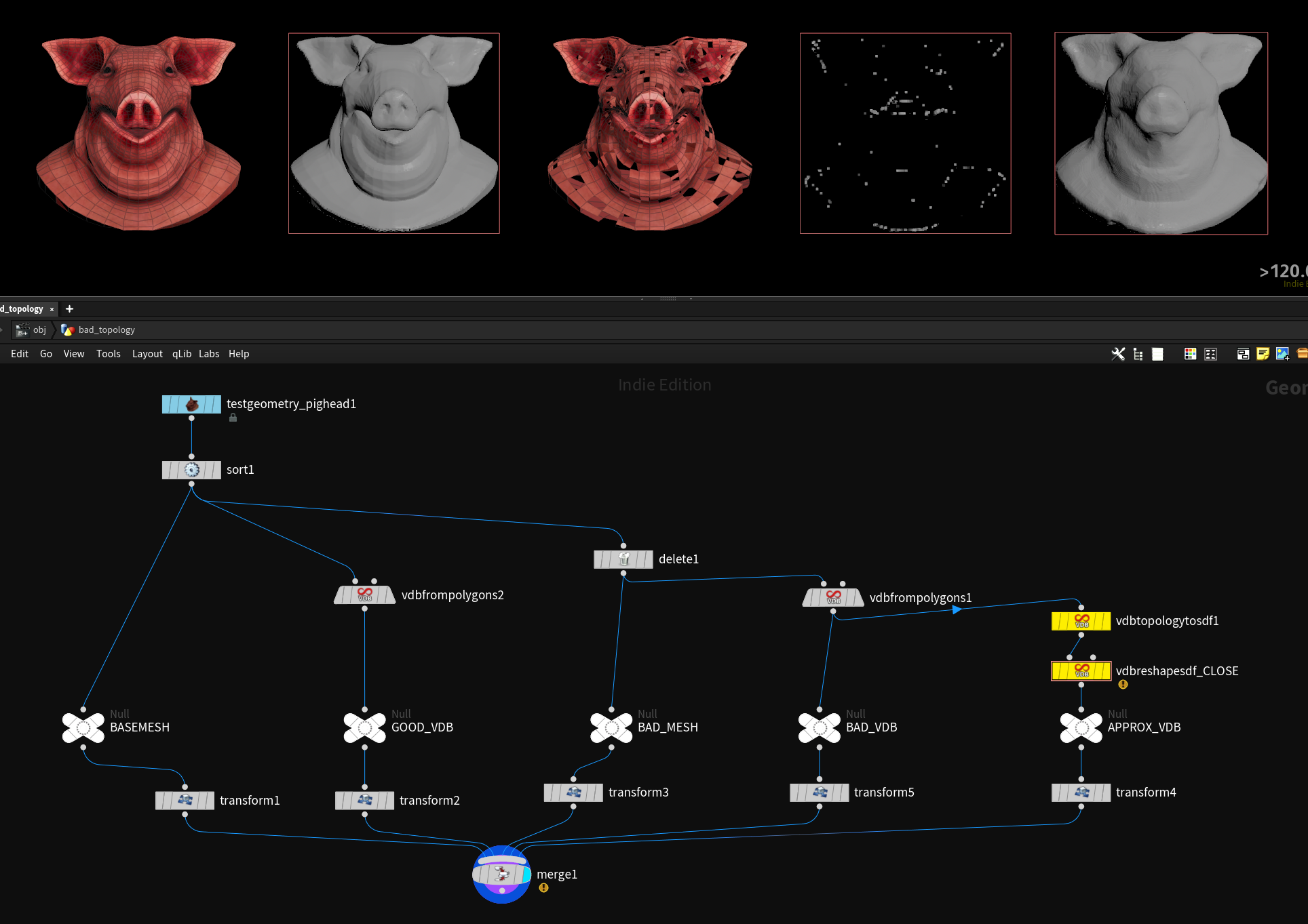
# Collision VDBs from Bad Topology
When dealing with bad or damaged / ’non watertight’ topology you can use the VDB Topology to SDF node to approximate a surface from the bad vdb result you get from the VDB from Polygons node.
# Performance
To avoid regenerating collision geometry / vdbs of a moving but nondeforming object it makes sense to avoid SOP level animation and only animate on OBJ level and use the transform to move the collider in the DOP network. To do so you have to point the OBJ Path Parameter in the static object to the geo node containing your collider and enable Use Object Transform. This speeds up collider calculations massively. However you will lose per point collider velocities, because the geometry isn’t moving in SOPs.
sources / further reading: